Gamma3 Long Nail R2.0 Operative Technique - Stryker
Gamma3 Long Nail R2.0 Operative Technique - Stryker
Gamma3 Long Nail R2.0 Operative Technique - Stryker

Create successful ePaper yourself
Turn your PDF publications into a flip-book with our unique Google optimized e-Paper software.
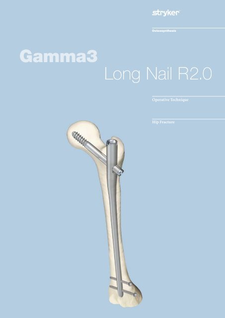
<strong>Gamma3</strong> <strong>Long</strong> <strong>Nail</strong> <strong>R2.0</strong><br />
<strong>Operative</strong> <strong>Technique</strong><br />
Hip Fracture
<strong>Long</strong> <strong>Nail</strong> R .0<br />
Contributing Surgeons:<br />
Prof. Kwok Sui Leung, M. D.<br />
Chairman of Department of Orthopaedics and Traumatology<br />
The Chinese University of Hong Kong<br />
Prince of Wales Hospital<br />
Hong Kong<br />
Dr. Gilbert Taglang<br />
Head of the Trauma Department<br />
Center for Traumatology, Strasbourg<br />
France<br />
Prof. Dr. med. Volker Bühren<br />
Chief of Surgical Services<br />
Medical Director of Murnau Trauma Center, Murnau<br />
Germany<br />
Katsumi Sato M.D.Ph.D.<br />
Vice-Director, Chief Surgeon<br />
Tohoku University Graduate School of Medicine<br />
Tohoku Rosai Hospital, Sendai<br />
Japan<br />
Christopher T. Born M.D.<br />
Professor of Orthopaedic Surgery<br />
Temple University<br />
Philadelphia, PA<br />
USA<br />
Robert Probe, M.D.<br />
Division of Orthopaedic Surgery<br />
Scott & White Memorial Hospital, Temple, Tx<br />
USA<br />
Prof. Dr. med. Vilmos Vécsei<br />
Chief of Traumatology Department<br />
University of Vienna, Vienna<br />
Austria<br />
This publication sets forth detailed<br />
recommended procedures for<br />
using <strong>Stryker</strong> Trauma devices and<br />
instruments.<br />
It offers guidance that you should<br />
heed, but, as with any such technical<br />
guide, each surgeon must consider the<br />
particular needs of each patient and<br />
make appropriate adjustments when<br />
and as required. A workshop training<br />
is required prior to first surgery.<br />
Note:<br />
All bone screws referenced in this<br />
material here are not approved for<br />
screw attachment or fixation to the<br />
posterior elements (pedicles) of the<br />
cervical, thoracic or lumbar spine.
Contents<br />
Introduction<br />
Design Features of the <strong>Gamma3</strong> System<br />
Lag Screw and Set Screw Function<br />
Distal Locking Screws<br />
<strong>Gamma3</strong> System Benefits<br />
Indications/Contraindications<br />
<strong>Operative</strong> <strong>Technique</strong><br />
Implant Selection<br />
Patient Positioning and Fracture Reduction<br />
Special <strong>Technique</strong>s for Fracture Reduction<br />
Incision<br />
Entry Point<br />
Preparation of Medullary Canal<br />
One Step Conical Reamer<br />
Cannulated Cutter<br />
Assembly of Targeting Device<br />
<strong>Nail</strong> Insertion and Positioning<br />
Lag Screw Positioning using One Shot Device<br />
Lag Screw Insertion<br />
Lag Screw Fixation<br />
Distal Screw Locking<br />
End Cap Insertion<br />
<strong>Nail</strong> Extension End Caps<br />
Postoperative Care and Rehabilitation<br />
Extraction of the <strong>Gamma3</strong> Implant<br />
Dealing with Special Cases<br />
Ordering Information – Implants<br />
Ordering Information – Instruments<br />
Publications<br />
3<br />
4<br />
5<br />
6<br />
7<br />
8<br />
9<br />
10<br />
11<br />
13<br />
14<br />
16<br />
16<br />
18<br />
20<br />
21<br />
24<br />
25<br />
26<br />
31<br />
34<br />
38<br />
39<br />
39<br />
40<br />
42<br />
43<br />
48<br />
51
Introduction<br />
Introduction<br />
The <strong>Gamma3</strong> Locking <strong>Nail</strong> System is<br />
based on more than 16 years of Gamma<br />
<strong>Nail</strong> experience. This is the third<br />
generation of intramedullary short<br />
and long Gamma fixation nails.<br />
The Evolution of the successful Trochanteric<br />
and <strong>Long</strong> Gamma <strong>Nail</strong>s as<br />
well as the Asia Pacific and Japanese<br />
versions followed strictly a step by<br />
step improvement based on the clinical<br />
experience of the clinical outcome<br />
from surgeons all over the world.<br />
The new <strong>Gamma3</strong> System is designed<br />
to facilitate minimally invasive surgery<br />
and reduce the OR time down to<br />
a minimum by the aid of using new<br />
instrumentation and an optimized<br />
surgical technique.<br />
The nails have a proximal diameter of<br />
15.5mm to help minimize the incision<br />
length required for minimally invasive<br />
surgery. Nevertheless, they offer<br />
the same biomechanical strength and<br />
cut-out resistance as the well established<br />
Trochanteric and <strong>Long</strong> Gamma<br />
<strong>Nail</strong>s.<br />
The new Lag Screw shape has been<br />
improved, especially in the area of the<br />
thread and the cutting flutes at the tip<br />
of the screw. The new design offers<br />
superior cutting behavior during Lag<br />
Screw insertion, providing extremely<br />
low insertion torque. The new thread<br />
design also offers excellent grip in the<br />
cancellous bone of the femoral head<br />
and strong resistance against cut-out.<br />
The 5mm distal locking screws are<br />
currently used in the Gamma-Ti and<br />
the T2 intramedullary nailing systems.<br />
A major advantage of the system is the<br />
newly designed instrument platform.<br />
The instruments are designed for a<br />
minimally invasive surgical technique<br />
and reduce OR time to a minimum.<br />
The instruments are easy to use and<br />
easy to clean, and they share the same<br />
platform as the <strong>Stryker</strong> intramedullary<br />
T2 and S2 nails.<br />
Acknowledgements:<br />
Our thanks are due to the many surgeons<br />
who supported the development<br />
of the new <strong>Gamma3</strong> System, with their<br />
feedback and ideas, during worldwide<br />
panel meetings and helped the<br />
<strong>Gamma3</strong> System to be what it is today.<br />
Special thanks to the Asian Pacific<br />
Technical Committee, who supported<br />
very early the idea of smaller implants<br />
for the treatment of proximal femur<br />
fractures.
Features<br />
Design Features of the <strong>Gamma3</strong><br />
System<br />
<strong>Gamma3</strong> Locking <strong>Nail</strong>s come in 3<br />
neck-shaft angles of 120, 125 and 130°.<br />
• In the following, these <strong>Gamma3</strong><br />
<strong>Nail</strong>s are called:<br />
<strong>Long</strong> <strong>Nail</strong><br />
All nails* use the same Lag Screws, Set<br />
Screw, distal Locking Screws and End<br />
Caps (see Fig. 1).<br />
<strong>Gamma3</strong> <strong>Nail</strong> <strong>Long</strong><br />
This nail incorporates several important<br />
mechanical design features. The<br />
nail is unslotted and cannulated for<br />
Guide-Wire-controlled insertion. To<br />
facilitate conformity with the human<br />
anatomy, the <strong>Long</strong> <strong>Nail</strong> is supplied in a<br />
left and right version.<br />
The three neck-shaft angles accommodate<br />
variations in femoral neck<br />
anatomy. The <strong>Long</strong> <strong>Nail</strong> offers the<br />
opportunity to use two distal Locking<br />
Screws that are inserted through the<br />
distal nail end to control rotation and<br />
telescoping. As shown below, the nail<br />
offers the possibility for either static,<br />
dynamic or secondary dynamic distal<br />
locking, depending on the fracture<br />
pattern.<br />
<strong>Long</strong> <strong>Nail</strong> Distal Locking Options<br />
* Each nail is supplied sterile packaged together with a Set Screw in one box.<br />
• Material:<br />
Titanium alloy with anodized type<br />
II surface treatment or Orthinox®<br />
High Strength Stainless Steel<br />
• <strong>Nail</strong> length:<br />
280mm to 460mm, in 20mm<br />
increments, shorter or longer nails<br />
are available on request<br />
• <strong>Nail</strong> diameter:<br />
proximal 15.5mm, distal: 11.0mm<br />
• Proximal <strong>Nail</strong> angle range:<br />
120°, 125°, 130°<br />
• M-L bend for valgus curvature:<br />
4 degrees<br />
• Proximal anterversion of 10°<br />
• End Caps<br />
0mm, +5mm and +10mm<br />
• Antecurvature radius R .0m of<br />
the shaft<br />
• Distal locking holes<br />
(round and oblong)<br />
for 5mm screws; up to 5mm<br />
dynamization is possible<br />
• Locking in the distal part of the oblong hole creates a dynamic locking<br />
mechanism − requires only one screw (see Fig. 2).<br />
• One screw placed in the distal part of the oblong hole and the other in the<br />
round hole.<br />
If dynamization is required after a period of time, the screw, placed in the<br />
round hole, has to be removed − requires two screws (see Fig. 3).<br />
• One screw placed in the round hole and the other is placed in the proximal<br />
part of the oblong hole − requires two screws (see Fig. 4).<br />
Fig. 2<br />
Dynamic Locking<br />
Fig. 3<br />
Secondary Dynamization<br />
Technical Specifications:<br />
Remove this screw to<br />
allow for dynamization<br />
Fig. 4<br />
Static Locking<br />
Distal Locking Screws<br />
<strong>Gamma3</strong> End Cap<br />
<strong>Gamma3</strong> Set Screw<br />
120°<br />
125°<br />
130°<br />
<strong>Gamma3</strong> Lag Screw<br />
<strong>Gamma3</strong> <strong>Long</strong> <strong>Nail</strong><br />
Fig. 1
Features<br />
Fig. 5<br />
Lag Screw Stabilization System<br />
Lag Screw and<br />
Set Screw Function<br />
The Lag Screws are designed to<br />
transfer the load of the femoral head<br />
into the nail shaft by bridging the<br />
fracture line to allow fast and secure<br />
fracture healing. The load carrying<br />
thread design of the <strong>Gamma3</strong> Lag<br />
Screw provides large surface contact to<br />
the cancellous bone. This provides<br />
high resistance against cut out.<br />
<strong>Gamma3</strong> Lag Screws feature a special<br />
tip profile to allow use with bone<br />
substitutes and the self-tapping thread<br />
is designed for easy insertion.<br />
The patented Set Screw is designed to<br />
fit into one of the four grooves of the<br />
shaft of the Lag Screw. This prevents<br />
both, rotation and medial migration<br />
of the Lag Screw.<br />
The nail allows sliding of the Lag<br />
Screw to the lateral side for dynamic<br />
bone compression at the fracture site<br />
to enhance fracture healing.<br />
Technical Specifications<br />
• Lag Screw diameter: 10.5mm<br />
• Lag Screw lengths: 70−120mm in<br />
5mm increments<br />
• Patented Lag Screw design for high<br />
load absorption and easy insertion<br />
• Asymmetrical depth profile to allow<br />
the Lag Screw to slide in the lateral<br />
direction only (see orange arrow on<br />
Fig. 5).<br />
• Patented self retaining Set Screw to<br />
secure the Lag Screw against<br />
rotation and simultaneously<br />
allowing sliding of the Lag Screw<br />
laterally.
Features<br />
Distal Locking Screws<br />
The distal Locking Screw has a short<br />
self-tapping tip which facilitates a<br />
faster and easier start as well as easy<br />
screw insertion. It promotes excellent<br />
surface to bone contact (Fig. 6).<br />
Fig. 6<br />
The screw has an external diameter<br />
of 5mm, and provides an even higher<br />
fatigue strength than the clinically<br />
successful 6.28mm Locking Screw<br />
of the regular Gamma and G /K<br />
Locking <strong>Nail</strong> System (data on file).<br />
The screw diameter directly under the<br />
screw head has been reduced to<br />
prevent radial pressure that may cause<br />
micro fractures during screw insertion<br />
when the screw head reaches its final<br />
position. This reduction in diameter<br />
also improves the feel on the final<br />
tightening of the screw (Fig. 6a).<br />
Length Definition of<br />
the Distal Locking Screw<br />
The distal Locking Screw is measured<br />
from head to tip (Fig. 6b).<br />
Technical Specifications<br />
• Distal Locking Screw Diameter:<br />
5mm.<br />
• Distal Locking Screw lengths<br />
ranging from 25−50mm, in 2.5 and<br />
5mm increments. <strong>Long</strong>er screws up<br />
to 120mm are available on request.<br />
• Fully threaded screw design.<br />
Partially threaded screws are<br />
available on request<br />
• Self-tapping screw tip with<br />
optimized short cutting flutes.<br />
• Optimized diameter under the<br />
head helps to prevent microfractures<br />
during insertion.<br />
5mm<br />
Length Definition<br />
Reduced diameter<br />
Fig. 6a<br />
Fig. 6b
Features<br />
<strong>Gamma3</strong> System Benefits<br />
Strength and Stability<br />
The biomechanical superiority of the<br />
intramedullary system offers significantly<br />
greater strength and stability<br />
compared with the side plate, in<br />
clinical use [1]. The new <strong>Gamma3</strong><br />
system offers the same strength as the<br />
well established Gamma Locking <strong>Nail</strong><br />
System.<br />
[1] K.S.Leung et al, Multicenter Trial<br />
of the Modified Gamma <strong>Nail</strong> in East<br />
Asia CORR323: 146−154,1996<br />
D<br />
D > d<br />
d<br />
The Biomechanical Advantage<br />
over Side-Plate Systems<br />
Since the load-bearing axis of the<br />
<strong>Gamma3</strong> <strong>Nail</strong> is closer to the hip joint<br />
fulcrum, the effective lever arm on the<br />
implant and femur is significantly<br />
shorter than with an extramedullary<br />
plate. The reduction factor is equivalent<br />
to d/D as shown in Figure 7 (approximately<br />
25% [1]).<br />
The resultant force is transmitted<br />
directly down the femur using a nail<br />
system. If a side-plate system is used,<br />
the femur shaft may be weakened<br />
through a high amount of locking<br />
screws. The <strong>Gamma3</strong> <strong>Nail</strong> increases<br />
both the strength and reliability of the<br />
bio-mechanical repair. The distal<br />
dynamic locking option additionally<br />
allows the use of dynamic<br />
compression.<br />
Fig. 7<br />
Rehabilitation Benefits<br />
The extra strength effectively gained<br />
through the biomechanics of the<br />
<strong>Gamma3</strong> System combined with<br />
improved control of axial telescoping<br />
and rotational instability may allow<br />
earlier weight-bearing even in patients<br />
with complex or unstable proximal<br />
and combined ipsilateral shaft<br />
fractures. Early mobilization, dynamic<br />
compression, and a less traumatic<br />
operative technique increase the<br />
chance for rapid recovery and reliable<br />
bone union.
<strong>Operative</strong> <strong>Technique</strong><br />
Indications /Contraindications<br />
Indications<br />
• Subtrochanteric fractures<br />
• Pertrochanteric fractures associated<br />
with shaft fractures<br />
• Pathological fractures (including<br />
prophylactic use) in both trochan-<br />
teric and diaphysal areas<br />
• Nonunion and malunion<br />
Contraindications<br />
Contraindications are medial neck<br />
fractures.<br />
Note:<br />
If no bone consolidation occurs the<br />
system may fail. The aim of postoperative<br />
care must be to ensure the<br />
promotion of bone consolidation.<br />
The aim of this operative technique<br />
manual is to provide the surgeon with<br />
a simple step-by-step operating guide<br />
to aid in successful addition of the<br />
<strong>Gamma3</strong> System into their standard<br />
trauma care. Once the technique has<br />
been learned, the surgeon should find<br />
the operative procedure simple to<br />
implement. In fact, many of the basic<br />
principles for the <strong>Gamma3</strong> System<br />
are those employed for all closed intramedullary<br />
nailing procedures.<br />
This operative technique has been<br />
devised in consultation with leading<br />
surgeons in many countries to be<br />
a basic guide, particularly for less<br />
experienced users of the <strong>Gamma3</strong><br />
System. It is acknowledged that<br />
several alternative approaches to certain<br />
elements of the procedure are<br />
available, and may have advantages for<br />
particular situations or surgeons.<br />
Fig. 8
<strong>Operative</strong> <strong>Technique</strong><br />
Fig. 9<br />
X-ray in a-p view,<br />
showing implant<br />
Implant Selection<br />
The <strong>Gamma3</strong> <strong>Nail</strong> with a 125° nail<br />
angle may be used in the majority of<br />
patients. The 120° nail may be needed<br />
in patients with osteoarthritic coxa<br />
vara, and the 130° nail for coxa valga.<br />
Where such variations in femoral<br />
anatomy require an alternative, the<br />
following chapter describes how to<br />
select the optimal implant size.<br />
Preoperative Planning<br />
X-ray templates are very helpful<br />
during preoperative planning. Use the<br />
X-ray Templates (Fig. 9a) for short and<br />
long nails to select the correct implant<br />
and the optimal nail angle.<br />
These templates show the true implant<br />
size at a magnification of 15% in<br />
anterior-posterior view. The X-rays<br />
should be taken at this magnification<br />
(15%) for an optimum surgical<br />
outcome (see Fig. 9). If accurate anatomical<br />
reduction has been achieved,<br />
the X-ray can be taken from the fractured<br />
hip or from the contralateral<br />
side.<br />
Alternatively the femoral neck angle,<br />
i.e. the angle between the femoral<br />
shaft mid-axis and the femoral neck<br />
mid-axis, could be measured using a<br />
goniometer. The nail length may also<br />
be determinated intraoperatively using<br />
the Guide Wire Ruler together with<br />
the Guide Wire.<br />
10<br />
Fig. 9a<br />
<strong>Gamma3</strong> <strong>Long</strong> <strong>Nail</strong> X-ray Template<br />
(Ref. No 1320-0005)<br />
Note:<br />
Please ensure precise alignment of<br />
the affected hip joint when using<br />
these templates. Template magnification<br />
is 15 %. All dimensions (nail<br />
angle and implant sizing) resulting<br />
from using these templates must be<br />
verified intraoperatively to ensure<br />
proper implant selection.
<strong>Operative</strong> <strong>Technique</strong><br />
Patient Positioning and<br />
Fracture Reduction<br />
The procedure for patient positioning<br />
is usually similar to that of a subtrochanteric<br />
fracture, however, in fractures<br />
that are particularly difficult to<br />
reduce, a transcondylar sterile Steinmann<br />
pin may be used. The pin is<br />
fixed directly to the orthopaedic table<br />
by an adaptable stirrup, and traction is<br />
applied until anatomical reduction in<br />
the A-P view is obtained (Fig. 10).<br />
The patient is placed in a supine position<br />
on the fracture table and closed<br />
reduction of the fracture is recommended<br />
(Fig. 10a).<br />
Traction is applied to the fracture,<br />
keeping the leg straight. The upper<br />
trunk should be flexed to the opposite<br />
side so that the fracture can be<br />
reduced by not too much adduction of<br />
the lower limb. It also gives easy access<br />
to the greater trochanter.<br />
11<br />
Fig. 10<br />
Fig. 10a
<strong>Operative</strong> <strong>Technique</strong><br />
1<br />
Fig. 11<br />
Fig. 11a<br />
Patient Positioning and<br />
Fracture Reduction<br />
Maintaining traction, the leg is internally<br />
rotated 10−15 degrees to complete<br />
fracture reduction; the patella<br />
should have either a horizontal or<br />
slightly inward position (Fig. 11).<br />
Position the image intensifier so that<br />
anterior-posterior and mediolateral<br />
views of the trochanteric region of the<br />
affected femur can be easily obtained.<br />
This position is best achieved if the<br />
image intensifier is positioned so that<br />
the axis of rotation of the intensifier is<br />
centered on the femoral neck of the affected<br />
femur (Fig. 11a). The views of<br />
the distal femur should also be easily<br />
obtained for distal locking.<br />
It is important to ensure that a view<br />
of both the distal and proximal tips<br />
of the nail can be obtained during the<br />
procedure without obstruction by the<br />
traction table.<br />
The patient is then prepared and<br />
draped as for standard femoral nailing<br />
procedures. When positioning the<br />
drapes, bear in mind that the incision<br />
will be more proximal.<br />
Note:<br />
Reduction should be achieved as anatomically as possible. If this is not<br />
achievable, reduction should be achieved at least in one plane. Reduction in the<br />
other plane may be achieved with the <strong>Gamma3</strong> <strong>Long</strong> <strong>Nail</strong> during insertion.
<strong>Operative</strong> <strong>Technique</strong><br />
Special <strong>Technique</strong>s for<br />
Fracture Reduction<br />
For specific situations, special<br />
techniques have been developed<br />
for fracture reduction, that are<br />
explained below.<br />
To counter this misalignment, the<br />
trunk is turned to the opposite side<br />
and held in position by a thoracic rest<br />
or by a large drape. This tightens the<br />
gluteus medius muscles and relaxes<br />
the psoas, externally rotating the<br />
proximal fragment into alignment<br />
and exposing the trochanter for easier<br />
introduction of the nail. The fractured<br />
limb is kept straight, with the knee in<br />
flexion (Fig. 12), using the stirrup to<br />
avoid adduction. This position helps<br />
to align the distal portion. Reduction<br />
is confirmed in the AP view.<br />
Subtrochanteric fractures cannot<br />
always be reduced during positioning<br />
in the lateral view, because the<br />
proximal fragment is drawn forward<br />
by tension from the psoas muscles.<br />
This may be reduced during surgery<br />
by using the Universal Rod (Fig. 12a).<br />
Care must be taken when introducing<br />
the implant as the proximal fragment<br />
may rotate during insertion.<br />
13<br />
Fig. 12<br />
Fig. 12a
<strong>Operative</strong> <strong>Technique</strong><br />
1<br />
Fig. 13<br />
Fig. 14<br />
Fig. 15<br />
Fig. 16<br />
Incision<br />
Incisions may be developed in<br />
different manners. Two alternatives<br />
will be described below.<br />
Alternative 1:<br />
The tip of the greater trochanter may<br />
be located by palpation (Fig. 13) and<br />
a horizontal skin incision of approximately<br />
2−3cm is made from the<br />
greater trochanter in the direction<br />
of the iliac crest (Fig. 14). In obese<br />
patients the incision length may need<br />
to be longer, depending on obesity of<br />
the patient.<br />
A small incision is deepened through<br />
the fascia lata, splitting the abductor<br />
muscle approximately 1−2cm immediately<br />
above the tip of the greater trochanter,<br />
thus exposing its tip. A selfretaining<br />
retractor, or tissue protection<br />
sleeve is put in place.<br />
Alternative :<br />
A long and thin metal rod (e. g. Screw<br />
Scale, <strong>Long</strong>) is placed on the lateral side<br />
of the leg. Check with image intensifier,<br />
using l-m view, that the metal rod<br />
is positioned parallel to the bone in the<br />
center of the proximal part of the<br />
femoral canal (Fig. 16a). A line is drawn<br />
on the skin (Fig. 16).<br />
Fig. 16a
<strong>Operative</strong> <strong>Technique</strong><br />
The C-arm is turned approx. 90° to<br />
provide an A-P image of the tip of<br />
the trochanter using the metal rod as<br />
shown in Fig. 17 and 17a.<br />
Fig. 17a<br />
A vertical line is drawn onto the skin<br />
(Fig. 18). The intersection of the lines<br />
indicates the position for the entry<br />
point of the nail. This is usually the<br />
anterior third of the tip of the greater<br />
trochanter as shown in Fig. 22.<br />
The skin incision is made cranially to<br />
the indicated intersection, following<br />
the sagital line in cranial direction.<br />
The distance between the intersection<br />
and the starting point for the incision<br />
differs, depending on the obesity of<br />
the patient. Under normal conditions<br />
it is a distance of approximately 2 cm.<br />
A small skin incision is made as<br />
described in Alternative 1 and shown<br />
in Fig. 20.<br />
1<br />
Fig. 17<br />
Fig. 18<br />
Fig. 19<br />
Fig. 20
<strong>Operative</strong> <strong>Technique</strong><br />
anterior 1 /3 2 /3 posterior<br />
1<br />
Fig. 21<br />
Fig. 22<br />
Fig. 23<br />
Incision<br />
Using a finger, the tip of the trochanter<br />
should be felt easily (Fig. 21).<br />
Entry Point<br />
The correct entry point is located at<br />
the junction of the anterior third and<br />
posterior two-thirds of the tip of the<br />
greater trochanter and on the tip itself<br />
(Fig. 22).<br />
Preparation of the<br />
Medullary Canal<br />
In order to prepare the medullary<br />
canal for the <strong>Gamma3</strong> <strong>Long</strong> <strong>Nail</strong>,<br />
3 possibilities are described in the next<br />
chapters.<br />
Alternative 1:<br />
Opening the Cortex<br />
The medullary canal has to be opened<br />
under image intensification. The use<br />
of the cannulated Curved Awl (Fig. 23)<br />
is recommended if conventional<br />
reaming or the One Step Conical<br />
Reamer will be used to prepare the<br />
canal for the nail.
<strong>Operative</strong> <strong>Technique</strong><br />
Reaming the Medullary Canal<br />
A 3mm ball-tipped Guide-Wire is<br />
recommended as a reamer guide.<br />
Pass the reamer Guide Wire through<br />
the cannulated curved awl into the<br />
shaft of the femur as shown, using the<br />
Guide Wire Handle (Fig. 24).<br />
Rotating the Guide Wire during insertion<br />
makes it easier to achieve the<br />
desired position in the middle of the<br />
medullary canal.<br />
Flexible reamers are used to ream the<br />
shaft of the femur in stages starting<br />
from 9mm diameter and increasing<br />
in 0.5mm increments (Fig. 25). The<br />
canal should be reamed at least 2mm<br />
larger than the distal diameter of the<br />
nail, 13mm for the <strong>Gamma3</strong> <strong>Long</strong><br />
<strong>Nail</strong> (Fig. 26).<br />
In order to accommodate the proximal<br />
part of the <strong>Gamma3</strong> <strong>Long</strong> <strong>Nail</strong>,<br />
the subtrochanteric region must be<br />
opened up to 15.5mm (Fig. 27). This<br />
can be done either by reaming with<br />
the <strong>Stryker</strong> BIXCUT Reaming<br />
System (Fig. 25) or, alternatively, with<br />
the One Step Conical Reamer. For<br />
soft tissue protection, the Conical<br />
Reamer Sleeve should be used during<br />
reaming.<br />
Care must be taken with flexible<br />
reamers to ensure that the Guide-<br />
Wire is not displaced laterally during<br />
reaming. This could lead to resection<br />
of more bone on the lateral side,<br />
which in turn would lead to an offset<br />
position for the nail and a risk of<br />
shaft fracture.<br />
Note:<br />
Where the shaft is comminuted,<br />
reaming should be stopped at<br />
the fracture site and penetration<br />
continued with the power drill off.<br />
Bixcut Reamer<br />
The complete range of Bixcut<br />
reamers is available with either<br />
modular or fixed heads.<br />
13mm<br />
13mm 15,5mm<br />
1<br />
approx. 80mm<br />
Fig. 25<br />
Fig. 24<br />
Fig. 26<br />
Fig. 27
<strong>Operative</strong> <strong>Technique</strong><br />
3mm Guide Wire<br />
or 3.2mm K-Wire One Step Conical Reamer<br />
K-Wire<br />
Multi Hole Trocar<br />
1<br />
Reamer Sleeve<br />
Fig. 28<br />
Fig. 29<br />
Alternative :<br />
One Step Conical Reamer<br />
The One Step Conical Reamer is an<br />
optional instrument and has been<br />
developed to provide surgeons with<br />
another option to prepare the<br />
proximal canal of the trochanter<br />
using only one drilling step.<br />
Using <strong>Gamma3</strong> <strong>Long</strong> <strong>Nail</strong>s, it is<br />
recommended to ream the medullary<br />
canal all the way down to the condyle<br />
area, at least up to a diameter of<br />
13mm.<br />
After skin incision and positioning<br />
of the Guide Wire as described<br />
above, the Trocar or Multi Hole<br />
Trocar is inserted into the Reamer<br />
Sleeve to protect the soft tissue<br />
during insertion. Push the Trocar<br />
(use center hole, if Multi Hole Trocar<br />
is used) and Sleeve Assembly down<br />
over the 3mm Guide Wire to the tip<br />
of the trochanter (Fig. 28 and 29).<br />
Entry Point Optimization<br />
The Entry Portal can also be made<br />
without using the awl. A 3.2mm<br />
K-Wire is placed through the tip of<br />
the trochanter.<br />
If you find that the K-Wire is not<br />
positioned in the optimal position, it<br />
may easily be corrected using a second<br />
K-Wire in combination with the<br />
Multi Hole Trocar.<br />
The Multi Hole Trocar has a special<br />
design for more precise insertion. In<br />
addition to the central hole, 4 other<br />
holes are located eccentrically at<br />
different distances from the center<br />
(Fig. 29) to easily revise insertion<br />
of the guiding K-Wire in the proper<br />
position (Entry Point).
<strong>Operative</strong> <strong>Technique</strong><br />
The Trocar is then removed and<br />
the One Step Conical Reamer is<br />
connected to the T-handle and slid<br />
over the Guide or K-Wire to the<br />
tip of the trochanter. With gentle<br />
clockwise turning and pushing<br />
movements, the Conical Reamer<br />
will drill into the proximal part of<br />
the trochanter (Fig. 30 and 31) and<br />
prepare the canal for the proximal<br />
part of the <strong>Gamma3</strong> <strong>Nail</strong>. The One<br />
Step Conical Reamer stops when the<br />
correct depth is reached.<br />
Note:<br />
The One Step Conical Reamer is a<br />
front and side cutting instrument<br />
and should be used with great care<br />
to ensure that the sharp edges of the<br />
reamer do not damage intact bone<br />
inadvertently.<br />
If a 3.2mm K-Wire was used it<br />
should be replaced by a Guide Wire<br />
afterwards.<br />
1<br />
Fig. 30<br />
Fig. 31
<strong>Operative</strong> <strong>Technique</strong><br />
0<br />
Fig. 32<br />
Alternative 3:<br />
Cannulated Cutter<br />
Opening the cortex<br />
The Cannulated Cutter is a front<br />
cutting device used to prepare the<br />
proximal part of the femur for the<br />
<strong>Gamma3</strong> <strong>Long</strong> <strong>Nail</strong>.<br />
It provides surgeons with an advanced<br />
option to open the proximal femur<br />
cavity without reaming. Especially in<br />
older patients it may reduce the<br />
requirement for reaming of the<br />
femoral cavity. For the <strong>Long</strong> <strong>Nail</strong>, it is<br />
recommended to ream the complete<br />
femur all the way down to the condyle<br />
area up to a diameter of at least<br />
13mm.<br />
The Cannulated Cutter is guided over<br />
a solid 4mm Guide Pin. The fixation<br />
of this Guide Pin in the bone allows<br />
for an optimal placement for the<br />
Cannulated Cutter.<br />
This device allows for easy collection<br />
of bone graft material which might be<br />
helpful in difficult healing conditions.<br />
Fig. 33
<strong>Operative</strong> <strong>Technique</strong><br />
Assembly of Targeting Device<br />
1. Targeting Sleeve and<br />
Knob Assembly<br />
First assemble the Knob to the<br />
Targeting Sleeve (Fig. 34) and adjust<br />
the point on the Knob to be in line<br />
with the arrow on the Targeting<br />
Sleeve. Push the knob hard against<br />
the sleeve (Fig. 34a). The Knob moves<br />
approximately 5mm to the sleeve<br />
and has to be turned clockwise by<br />
approximately 30 degrees. Release the<br />
Knob and it will slip back the same<br />
distance. Now the Knob is assembled<br />
to the Targeting Sleeve and has to be<br />
connected to the Targeting Arm<br />
(Fig. 34b).<br />
. Targeting Arm and Targeting<br />
Sleeve Assembly<br />
Slide the Sleeve assembly over the<br />
Targeting Arm along the line until it<br />
stops (arrow line to arrow line).<br />
Rotate the Targeting Sleeve around to<br />
the required nail angle position for the<br />
Lag Screw, e. g. 125° (point to point) or<br />
distal locking positions, either<br />
“Dynamic” or “Static”. Now the<br />
Targeting Sleeve must be fixed in this<br />
position by pushing it strongly against<br />
the Targeting Arm. You will feel and<br />
hear, as the sleeve snaps into position.<br />
The Knobs only function is to lock the<br />
Lag Screw Guide Sleeve and the Tissue<br />
Protection Sleeve.<br />
Note:<br />
The Knob has to be assembled first<br />
to the Targeting Sleeve (Fig. 34a),<br />
otherwise the locking function of the<br />
sleeve may not work properly.<br />
Targeting Arm<br />
Targeting Sleeve 180<br />
green coded<br />
Knob<br />
Fig. 34<br />
1<br />
Fig. 34a Fig. 34b
<strong>Operative</strong> <strong>Technique</strong><br />
Ball Tip Screwdriver<br />
<strong>Nail</strong> Holding Screw<br />
Targeting Arm<br />
<strong>Gamma3</strong> <strong>Nail</strong> <strong>Long</strong><br />
Fig. 35<br />
<strong>Gamma3</strong> <strong>Long</strong> <strong>Nail</strong> Assembly<br />
3. Assembly of the Targeting<br />
Device and the <strong>Gamma3</strong> <strong>Long</strong> <strong>Nail</strong><br />
The selected <strong>Gamma3</strong> <strong>Long</strong> <strong>Nail</strong> is<br />
now assembled to the Carbon Fibre<br />
Targeting Device as shown in Figure<br />
35. The nail connecting part of the<br />
Targeting Device is designed with an<br />
easy assembly function for fast and<br />
secure nail fixation.<br />
Ensure that the locating pegs fit into<br />
the corresponding notches of the<br />
proximal part of the nail.<br />
Fully tighten the <strong>Nail</strong> Holding Screw<br />
with the Ball Tip Screwdriver, so<br />
that it does not loosen during nail<br />
insertion.<br />
Before starting surgery the following<br />
two functions of the Targeting Device<br />
have to be checked:<br />
1. Secure fixation between <strong>Nail</strong> and<br />
Targeting Device<br />
2. Lag Screw Guide Sleeve matches<br />
the selected nail angle.
<strong>Operative</strong> <strong>Technique</strong><br />
Before checking the function of the<br />
Lag Screw Guide Sleeve, the Knob<br />
must be positioned in the counter<br />
clockwise position. Pass the Lag Screw<br />
Guide Sleeve gently through the hole<br />
of the Targeting Sleeve and tighten it<br />
gently in its final position by turning<br />
the Knob clockwise. Check correct nail<br />
angle using the K-Wire, 4.2mm Drill<br />
or Lag Screw Step Drill (Fig. 36).<br />
Remove the Lag Screw Guide Sleeve by<br />
turning the Knob counter clockwise<br />
and pulling the sleeve back.<br />
Note:<br />
Before starting surgery, the implant<br />
and instrument assembly has<br />
to be checked. Ensure that the<br />
Targeting Sleeve angle matches the<br />
corresponding nail angle chosen, e. g.<br />
a 125° Targeting Sleeve for a 125° nail<br />
(Fig 36).<br />
Lag Screw Guide Sleeve<br />
3<br />
Fig. 36
<strong>Operative</strong> <strong>Technique</strong><br />
Fig. 37<br />
Fig. 38<br />
Fig. 39<br />
Fig. 40<br />
Fig. 41<br />
<strong>Nail</strong> Insertion and Positioning<br />
Insert the <strong>Gamma3</strong> <strong>Nail</strong> by hand<br />
(Fig. 37).<br />
DO NOT use undue force −<br />
NEVER use a hammer for<br />
nail insertion.<br />
The final nail depth is monitored with<br />
the image intensifier; the axis of the<br />
Lag Screw may be projected with a<br />
ruler on the monitor screen to ensure<br />
that the Lag Screw is placed in the<br />
optimal position.<br />
Proceed until the axis of the Lag<br />
Screw hole (visible as a crescent shape<br />
on the screen) is aligned with the<br />
lower half of the femoral neck (Fig.<br />
38). The objective of this is to ultimately<br />
position the Lag Screw slightly<br />
inferior in the femoral head in the<br />
frontal plane.<br />
Note:<br />
Make sure to remove the Guide Wire<br />
using the Guide Wire Handle (Fig. 39).<br />
When the <strong>Gamma3</strong> <strong>Nail</strong> has been<br />
inserted to its final depth, check the<br />
anteversion of the nail. Use of the<br />
K-Wire Clip (Fig. 40) or the “One Shot<br />
Device” is recommended (see next<br />
page).<br />
Lag Screw Positioning<br />
using the K-Wire Clip<br />
The K-Wire Clip is mounted in the<br />
slots of the Targeting Arm by pressing<br />
the Clip flanges together.<br />
Using image intensification of the<br />
lateral view, the projection of the<br />
U-Wire on the bone shows the A-P<br />
positioning of the Lag Screw.<br />
The Lag Screw should be placed in<br />
the central position of the femoral<br />
head(Fig. 41).<br />
Before proceeding ensure that the <strong>Nail</strong><br />
Holding Screw is still fully tightened.
<strong>Operative</strong> <strong>Technique</strong><br />
Lag Screw Positioning using<br />
the One Shot Device<br />
The One Shot Device is<br />
recommended for optimal Lag<br />
Screw placement:<br />
The One Shot Device is recommended<br />
for verifying that the Lag<br />
Screw is placed in its optimal<br />
position. This device enables correct<br />
positioning of the K-Wire for Lag<br />
Screw placement before performing<br />
lateral skin incision and opening of<br />
the lateral cortex. Figures 42−43a<br />
give an overview of the working<br />
principle of the One Shot Device.<br />
nail positioned<br />
too caudal<br />
optimal nail position<br />
nail positioned<br />
too cranial<br />
Fig. 42a<br />
A/P view<br />
Positioning of nail depth<br />
Positioning of anteversion<br />
Fig. 42<br />
Fig. 43<br />
Fig. 43a<br />
Lateral view
<strong>Operative</strong> <strong>Technique</strong><br />
Fig. 44<br />
Fig. 45<br />
Lag Screw Guide Sleeve in good contact to the lateral cortex<br />
Lag Screw Insertion<br />
The Targeting Device may be held<br />
by an assistant to prevent it from<br />
externally rotating the nail until the<br />
next stage is completed.<br />
Next, assemble the Lag Screw Guide<br />
Sleeve and the green coded 4.2mm<br />
Lag Screw Drill Guide Sleeve and pass<br />
them through the Targeting Sleeve<br />
to the level of the skin. At the point<br />
of contact, perform a small incision<br />
down to the bone (Fig. 44). The Guide<br />
Sleeve assembly is then advanced<br />
through the incision. If the sleeves<br />
catches the fascia lata, twisting it will<br />
usually allow it to pass through to the<br />
bone.<br />
In order to assure accurate Lag Screw<br />
length measurement, the outer<br />
Guide Sleeve must be in good contact<br />
to the lateral cortex of the femur<br />
(Fig. 45). The Knob of the Target<br />
Sleeve must be turned gently clockwise<br />
to lock the Guide Sleeve in place<br />
and further stabilize the targeting<br />
assembly.
<strong>Operative</strong> <strong>Technique</strong><br />
With the Lag Screw Guide Sleeve<br />
firmly engaged in the cortex, the green<br />
coded 4.2mm Lag Screw Drill Guide<br />
Sleeve should be pushed gently against<br />
the cortex. Using the green coded<br />
4.2mm × 300mm center tipped drill,<br />
the lateral cortex should be opened by<br />
power tool or by hand (Fig. 46).<br />
The green coded 4.2mm Lag Screw<br />
Drill Guide Sleeve is then replaced by<br />
the K-Wire Sleeve.<br />
Both sleeves look similar but have<br />
different inner hole diameters. The K-<br />
Wire Sleeve has no colored ring.<br />
K-Wire Sleeve<br />
Lag Screw Drill Guide Sleeve<br />
Note:<br />
Before proceeding, check that the<br />
Guide Wire for the flexible reamer<br />
and nail insertion used earlier has<br />
been removed.<br />
The single use K-Wire inserted<br />
through the K-Wire Sleeve should<br />
be advanced up to the subchondral<br />
bone (Fig. 48), using the Guide Wire<br />
Handle. Check that the K-Wire is<br />
placed in the lower half of the femoral<br />
head in the frontal plane and on the<br />
midline in the lateral plane (Fig. 48).<br />
Check the position with the image<br />
intensifier in both the anteriorposterior<br />
and mediolateral views as<br />
shown in Figure 38 to ensure optimal<br />
K-Wire positioning.<br />
uSE K-WIRE FOR ONE<br />
SuRGICAL PROCEDuRE ONLy<br />
Fig. 46<br />
Opening of the lateral cortex<br />
Fig. 47<br />
K-Wire placement<br />
<strong>Operative</strong> <strong>Technique</strong><br />
Fig. 49<br />
Lag Screw length measurement<br />
Fig. 50<br />
Lag Screw Length Measurement<br />
Lag Screw Insertion<br />
The objective is to position the Lag<br />
Screw below the center of the femoral<br />
head in the anterior-posterior view<br />
and centrally in the lateral view, to<br />
provide the best load transfer to the<br />
Lag Screw.<br />
After satisfactorily positioning the<br />
K-Wire, the required Lag Screw length<br />
is measured using the Lag Screw Ruler.<br />
Before starting to measure, ensure<br />
that the Lag Screw Guide Sleeve is still<br />
pressed firmly against the lateral cortex<br />
of the femur (Fig. 49).<br />
Place the Lag Screw Ruler directly<br />
under the K-Wire (Fig. 50).<br />
The recommended value for the Step<br />
Drill depth and the Lag Screw length<br />
can be read directly off the Lag Screw<br />
Ruler. If the value is between markings<br />
on the scale, e. g. 97mm, it should<br />
always be rounded up to the next<br />
higher value, e. g. 100mm.<br />
Note:<br />
K-Wires are not intended for re-use.<br />
They are single use only. K-Wires may<br />
be damaged or bent during surgical<br />
procedures. If a K-Wire is re-used, it<br />
may get lodged in the drill and could<br />
be advanced into the pelvis during<br />
the following steps of the procedure.<br />
This may damage large blood vessels<br />
or cause other serious injuries.
<strong>Operative</strong> <strong>Technique</strong><br />
The value of the measurement (Fig.<br />
50) is now transferred to the adjustable<br />
stop on the Lag Screw Step Drill.<br />
The value e. g. 100 must be visible in<br />
the window of the Step Drill Stop (Fig.<br />
51).<br />
The K-Wire Sleeve is now removed<br />
and the adjusted Lag Screw Step Drill<br />
is passed over the K-Wire (Fig. 51a),<br />
through the Lag Screw Guide Sleeve.<br />
The channel for the Lag Screw is<br />
prepared using the T-handle<br />
connected to the Lag Screw Step Drill.<br />
If exceptional resistance is encountered,<br />
a power drill may be used with<br />
great care.<br />
Drilling should continue until the stop<br />
of the Step Drill comes into contact<br />
with the Lag Screw Guide Sleeve (Fig.<br />
51a). Ensure that the Targeting Device<br />
is well supported to prevent it from<br />
slipping back or rotating.<br />
The drilling process, especially<br />
when the tip of the drill comes close<br />
to its final position in the femoral<br />
head, should be controlled under an<br />
image intensifier to avoid hip joint<br />
penetration. The K-Wire can also be<br />
observed in the K-Wire window of the<br />
Step Drill.<br />
Note:<br />
It is important to observe the K-Wire<br />
tip during drilling on the intensifier.<br />
The K-Wire window provides an<br />
additional possibility to double check<br />
the K-Wire end position. Ensure that<br />
under no circumstances the K-Wire is<br />
advanced into the pelvis.<br />
K-Wire end<br />
Lock<br />
K-Wire window<br />
Fig. 51<br />
Window of the Step Drill Stop<br />
K-Wire window<br />
Fig. 51a<br />
Lag Screw<br />
Guide Sleeve<br />
Lag Screw Step<br />
Drill Stop<br />
Groove indicates<br />
K-Wire end position
<strong>Operative</strong> <strong>Technique</strong><br />
30<br />
Fig. 52<br />
Fig. 53<br />
Lag Screw and Lag Screwdriver assembly<br />
Lag Screw Insertion<br />
During drilling, monitor the depth of<br />
the drill near the subchondral bone<br />
on image intensification. At this stage,<br />
you should see the tip of the K-Wire<br />
protruding about 6 to 10mm out of the<br />
step drill (Fig. 52) because the threaded<br />
portion of the K-Wire was intentionally<br />
not included in the drill measurement.<br />
This is to prevent the drill from<br />
penetrating the joint and to ensure<br />
that the K-Wire remains anchored in<br />
the subchondral bone after reaming.<br />
Remove the Step Drill by turning it<br />
clockwise and pulling it backwards.<br />
The length of the Lag Screw chosen<br />
should be the same as that of the Step<br />
Drill (in this example 100mm). The<br />
screw is then assembled to the Lag<br />
Screwdriver (Fig. 53).<br />
In a case where compression is to<br />
be applied, a shorter Lag Screw<br />
length should be chosen to avoid<br />
the Lag Screw sticking out too far<br />
out of the lateral cortex (see chapter<br />
Compression / Apposition below).<br />
Ensure that the pegs of the Lag<br />
Screwdriver are in the notches of the<br />
Lag Screw. The thumbwheel of the<br />
handle must be turned clockwise and<br />
finally tightened using the Ball Tip<br />
Screwdriver.<br />
The Lag Screw assembly is now passed<br />
over the K-Wire, through the Lag<br />
Screw Guide Sleeve and threaded up to<br />
the end of the predrilled hole into the<br />
femur head. Check the end position of<br />
the Lag Screw on the image intensifier.<br />
A double check of the end position is<br />
also possible with the indicator ring on<br />
the Lag Screw Screwdriver. The final<br />
position is obtained when the indicator<br />
ring reaches the end of the Lag Screw<br />
Guide Sleeve.
<strong>Operative</strong> <strong>Technique</strong><br />
Lag Screw Fixation<br />
The handle of the Lag Screwdriver<br />
must be either parallel or perpendicular<br />
(90°) to the Targeting Arm (Fig.<br />
55 on next page) to ensure that the Set<br />
Screw is able to fit into one of the four<br />
grooves of the Lag Screw shaft.<br />
The Set Screw alignment indicator<br />
will help to find the right position of<br />
the handle.<br />
If the T-handle is not perpendicular or<br />
parallel to the Targeting Arm, turn it<br />
clockwise until it reaches this position.<br />
NEVER TURN THE LAG SCREW<br />
COUNTER CLOCKWISE.<br />
If the K-Wire is inadvertently removed,<br />
the screw may still be inserted without<br />
it, provided that the Guide Sleeve is still<br />
in contact with the cortex.<br />
Note:<br />
It is strongly recommended to place<br />
the Lag Screw at the end of predrilled<br />
hole in order to provide maximal<br />
resistance against cut out. Never turn<br />
the Lag Screw counter clockwise after<br />
the final position is reached because<br />
otherwise the Lag Screw may lose full<br />
bony surface contact to its tip.<br />
Compression / Apposition<br />
If compression or apposition of the<br />
fracture gap is required, this can be<br />
achieved by gently turning the thumbwheel<br />
of the Lag Screwdriver clockwise<br />
against the Guide Sleeve (Fig. 54).<br />
Before starting compression, make<br />
sure that the Lag Screw Guide Sleeve is<br />
unlocked to allow its free sliding. To<br />
unlock the Lag Screw Guide Sleeve, the<br />
Knob of the Target Device has to be<br />
turned counter clock-wise. In<br />
osteoporotic bone care must be taken<br />
to prevent Lag Screw pullout in the<br />
femoral head. The Lag Screw should be<br />
chosen shorter depending on the<br />
expected amount of compression.<br />
31<br />
Fig. 54<br />
Compression / Apposition turning the thumbwheel clockwise.
<strong>Operative</strong> <strong>Technique</strong><br />
Set Screw Alignment Indicator<br />
3<br />
Fig. 56<br />
Set Screw insertion<br />
Fig. 55<br />
T-handle end position<br />
Lag Screw Fixation<br />
Note:<br />
The Set Screw must be used.<br />
The use of the Set Screw is not an<br />
option.<br />
Assemble the Set Screw to the Set<br />
Screw Driver. Insert the Set Screw<br />
as shown in Figure 56 along the<br />
opening of the post of the Targeting<br />
Device and advance it through the<br />
<strong>Nail</strong> Holding Screw.<br />
Push the Set Screw Driver down<br />
until you are sure, that the Set Screw<br />
engages the corresponding thread<br />
in the nail. During pushing down<br />
the assembly, you may feel a slight<br />
resistance.<br />
Turn the Screwdriver handle<br />
clockwise under continoues pressure.<br />
You may notice a slight resistance<br />
when turning the Set Screw. This is<br />
because the Set Screw thread is<br />
equipped with the “Nylstop” system<br />
to prevent spontaneous loosening.<br />
This is not the final position for the<br />
Set Screw.<br />
Keep on turning the Set Screw until<br />
you feel contact in one of the grooves<br />
of the Lag Screw.
<strong>Operative</strong> <strong>Technique</strong><br />
To verify the engagement the Set<br />
Screw in a groove of the Lag Screw,<br />
try to turn the Lag Screwdriver gently<br />
clockwise and counter-clockwise.<br />
If it is not possible to turn the Lag<br />
Screwdriver the Set Screw is engaged<br />
in one of the grooves. If the Lag Screw<br />
Driver still moves, recorrect the<br />
T-handle position and tighten the Set<br />
Screw again until it engages in one of<br />
the four Lag Screw grooves.<br />
After slightly tightening the Set Screw,<br />
it should then be unscrewed by one<br />
quarter (¼) of a turn, until a small<br />
play can be felt at the Lag Screwdriver.<br />
This ensures a free sliding of the Lag<br />
Screw.<br />
Make sure that the Set Screw is still<br />
engaged in the groove by checking that<br />
it is still not possible to turn the Lag<br />
Screw with the Lag Screwdriver.<br />
Note:<br />
Do not unscrew the Set Screw more<br />
than ¼ of a turn.<br />
If distal locking is not indicated, the<br />
End Cap should be assembled to the<br />
nail end to prevent bone ingrowth.<br />
Leaving the Lag Screwdriver in<br />
place, the <strong>Nail</strong> Holding Screw is<br />
now removed using the Ball Tip<br />
Screwdriver, Universal Socket Wrench<br />
or Spreading Screwdriver and turning<br />
it counter clockwise. Insert the End<br />
Cap (size 0) using the Socket Wrench,<br />
Spreading Screwdriver or the Ball Tip<br />
Screwdriver. The End Cap should be<br />
tightened slightly.<br />
Please see “End Cap Insertion” chapter.<br />
Alternatively the End Cap could also<br />
be inserted free hand after removal of<br />
the Target Device.<br />
33<br />
Fig. 57
<strong>Operative</strong> <strong>Technique</strong><br />
Fig. 58a<br />
Dynamic Locking<br />
Fig. 58b<br />
Secondary Dynamization<br />
Not in line with the <strong>Nail</strong> holes<br />
This is the best position to drill<br />
Not in line with the <strong>Nail</strong> holes<br />
This is the best position to drill; it shows correct view<br />
to be in line with the <strong>Nail</strong> holes<br />
3<br />
Fig. 58c<br />
Static Locking<br />
Fig. 58<br />
Fig. 59<br />
Fig. 60<br />
Distal Screw Locking<br />
<strong>Gamma3</strong> <strong>Long</strong> <strong>Nail</strong>s offer the<br />
possibility to be locked distally. For<br />
distal locking, the <strong>Long</strong> <strong>Nail</strong> offers the<br />
following three locking options (Fig.<br />
58), depending on the fracture pattern.<br />
<strong>Long</strong> <strong>Nail</strong> Distal Locking Options<br />
• Locking in the distal part of the<br />
oblong hole creates a dynamic<br />
locking mechanism − requires only<br />
one screw (see Fig. 58a).<br />
• One screw placed in the distal part<br />
of the oblong hole and the other in<br />
the round hole.<br />
If dynamization is required after a<br />
period of time, the screw, placed in<br />
the round hole, has to be removed −<br />
requires two screws (see Fig. 58b).<br />
• One screw placed in the round<br />
hole and the other is placed in the<br />
proximal part of the oblong hole −<br />
requires two screws (see Fig. 58c).<br />
Distal locking is recommended:<br />
• if the fracture is unstable<br />
• if rotational stability is required<br />
• if there is a wide disparity between<br />
the diameter of the nail and the<br />
femoral cavity.<br />
Various techniques can be used to<br />
guide drilling and insertion of screws<br />
through the distal holes. The freehand<br />
technique is described below.<br />
Visualizing the distal holes<br />
The essential initial step in distal<br />
targeting is to position the image<br />
intensifier so that the distal hole in<br />
the nail appears perfectly round.<br />
Naturally, this visualization steps<br />
refer to the appearance of the round<br />
and not the oblong hole. If the hole<br />
appears to be elliptical in either the<br />
vertical or horizontal plane, the image<br />
intensifier position must be adjusted<br />
appropriately as shown in Figures 59<br />
and 60.<br />
It is advised to correct image in one<br />
plane at a time.
<strong>Operative</strong> <strong>Technique</strong><br />
Free-hand <strong>Technique</strong><br />
The free-hand drill technique is used<br />
to fix the distal bone fragment to the<br />
nail using Locking Screws. Length and<br />
rotational alignment of the leg must<br />
be checked before locking the nail.<br />
The distal nail locking is described<br />
as follows, using the Static Locking<br />
mode according to Figures 61−63. Skin<br />
incisions are made in line with the<br />
distal holes of the nail.<br />
Once the image intensifier is correctly<br />
positioned as shown in Figures<br />
59 and 60, use the centre tipped<br />
Ø4.2mm×180mm, green coded drill<br />
and place the tip of the drill at an<br />
oblique angle to the centre of the hole<br />
(Fig. 61). Verify the position by X-ray<br />
and move the drill into the same plane<br />
as the holes in the nail, then drill<br />
through the first cortex and the nail<br />
until resistance of the second cortex is<br />
felt as shown in Figure 62.<br />
Alternatively, the drill can be drilled<br />
through the second cortex while<br />
viewing the image intensifier. The<br />
screw length can then be read directly<br />
from the Screw Scale on the drill<br />
(Fig. 64).<br />
If the Tissue Protection Sleeve is used<br />
with the drill, it has to be removed for<br />
the measurement.<br />
It is also possible to measure the<br />
correct screw length using the Free<br />
Hand Screw Gauge. After drilling<br />
through the second cortex, remove the<br />
drill and advance the small hook of the<br />
Screw Gauge through the holes behind<br />
the medial cortex and read out the<br />
required locking screw length.<br />
Insert the 5mm distal Locking Screw<br />
through the skin by using the 3.5mm<br />
Screwdriver; advance the screw head<br />
carefully until it is just in direct<br />
contact with the cortex (Fig. 65).<br />
Note:<br />
Take care not to overtighten.<br />
The screw head should just come<br />
into contact with the cortex and<br />
resistance should be felt.<br />
Fig. 62<br />
add thickness of the cortex<br />
(approx +5mm) to the read out value<br />
3<br />
anterior<br />
posterior<br />
Fig. 61<br />
Fig. 63<br />
direct read out<br />
Fig. 64<br />
Fig. 65
<strong>Operative</strong> <strong>Technique</strong><br />
3<br />
Fig. 66<br />
Fig. 67<br />
Alternative<br />
Alternatively Condyle Screws could<br />
be used for distal locking. If a<br />
Condyle Screw will be inserted, both<br />
cortices are drilled to a diameter of<br />
5mm using the Ø5×230mm Drill in<br />
a free-hand drill technique.<br />
After drilling through the second<br />
cortex, remove the drill and advance<br />
the small hook of the Screw Gauge<br />
through the holes behind the medial<br />
cortex and read out the required<br />
condyle screw length (see Fig. 66).<br />
Note:<br />
The measurement equals Condyle<br />
Screw fixation length (from top of<br />
the Condyle Screw head to the top<br />
of Condyle Nut head, as shown in<br />
Fig. 66). The Condyle Screw length<br />
is defined with the Condyle Screw<br />
tip flush to the Condyle Nut head.<br />
The possible fixation length can<br />
be 2mm longer than the Condyle<br />
Screw length or 5mm shorter.<br />
Please ensure that the Condyle Nut<br />
is tightened a minimum of 5 turns<br />
on the Condyle Screw!<br />
Examples:<br />
Measurement Condyle Screw Length<br />
(mm) (mm)<br />
56 55<br />
57 55 or 60<br />
58 60<br />
59 60<br />
The Condyle Screw K-Wire<br />
Ø1.8×310mm inserted from the<br />
lateral side to the medial side. At the<br />
medial point of the perforation, a<br />
skin incision is made for the Condyle<br />
Screw. From the medial side, the<br />
Condyle Screw is now brought<br />
forward over the Condyle Screw K-<br />
Wire and inserted using the Condyle<br />
Screw Screwdriver.<br />
Insert the Condyle Nut over the K-<br />
Wire using the other Condyle Screw<br />
Screwdriver (Fig. 67).<br />
Alternatively, if patient anatomy<br />
allows, the Condyle Screw may be<br />
introduced from lateral to medial in a<br />
similar manner as described above.
<strong>Operative</strong> <strong>Technique</strong><br />
Using both Condyle Screw<br />
Screwdrivers, the Condyle Nut and the<br />
Condyle Screw are tightened. Once<br />
tightened, the K-Wire is removed.<br />
The adjustable screw washers of the<br />
Condyle Screw and the Condyle<br />
Nut adapt to the surface of the bone.<br />
3<br />
Fig. 68
<strong>Operative</strong> <strong>Technique</strong><br />
3<br />
Fig. 69<br />
End Cap assembly<br />
Fig. 70<br />
Final <strong>Nail</strong> assembly<br />
End Cap Insertion<br />
It is recommended to use an End Cap<br />
to close the proximal part of the nail to<br />
prevent bone ingrowth.<br />
Remove the <strong>Nail</strong> Holding Screw using<br />
the Ball Tip Screwdriver, Spreading<br />
Screwdriver, Universal Socket Wrench<br />
or Strike Plate. Load the End Cap (size<br />
0) to one of the Screwdrivers and pass<br />
the assembly through the top of the<br />
Targeting Device down into the nail.<br />
Turn the handle clockwise until<br />
it stops mechanically. Remove the<br />
Screwdriver and remove the Targeting<br />
Device in cranial direction.<br />
Alternatively the End Cap could also<br />
be inserted free hand after removal of<br />
the Targeting Device.
<strong>Operative</strong> <strong>Technique</strong><br />
<strong>Nail</strong> Extension End Caps<br />
If the proximal end of the nail is<br />
completely sunk in the trochanter,<br />
End Caps in size +5mm and +10mm<br />
are available and can be assembled to<br />
the nail instead of the End Cap size<br />
0, to achieve cortical bone support<br />
proximally. The proximal part of<br />
the nail will be elongated by 5mm or<br />
10mm.<br />
These elongation End Caps are<br />
assembled using the Strike Plate with<br />
the self-retaining ring, the Spreading<br />
Screwdriver or Ball Tip Screwdriver.<br />
This can only be done if the Targeting<br />
Device is already removed from the<br />
nail.<br />
Postoperative Care<br />
and Rehabilitation<br />
Active and passive mobilization of the<br />
lower limbs may be started<br />
immediately. The injured limb should<br />
be kept elevated.<br />
For stable fractures that are locked<br />
statically or dynamically, full weight<br />
bearing walking may be started<br />
immediately.<br />
For unstable fractures with static<br />
locking, immediate full weight bearing<br />
walking is allowed in fractures with<br />
good bone contact.<br />
For fractures with poor bone contact<br />
due to comminution, partial weightbearing<br />
walking is allowed for the<br />
first 6 to 8 weeks. Full weight bearing<br />
walking can be commenced when<br />
there is a bridging callus formed as<br />
evident on the follow up X-ray.<br />
End Cap (size +10mm)<br />
End Cap (size +5mm)<br />
3<br />
Fig. 71
<strong>Operative</strong> <strong>Technique</strong><br />
0<br />
Fig. 72<br />
Fig. 73<br />
Fig. 74<br />
Extraction of the<br />
<strong>Gamma3</strong> Implant<br />
Where implant extraction is indicated,<br />
please proceed as follows:<br />
Step I (Fig. )<br />
Remove the distal screw using the<br />
3.5mm Screwdriver after making an<br />
incision through the old scar.<br />
Step II (Fig. 3)<br />
Make a small incision through the<br />
old scar below the greater trochanter<br />
to expose the outer end of the Lag<br />
Screw. Remove any bony ingrowth<br />
which may be obstructing the outer<br />
end or internal thread of the Lag<br />
Screw as necessary to enable the Lag<br />
Screwdriver to engage fully.<br />
The K-Wire is then introduced via the<br />
Lag Screw into the head of the femur.<br />
The Lag Screwdriver is passed over the<br />
K-Wire, using the Lag Screw Guide<br />
Sleeve as a Tissue Protector, and<br />
engaged with the distal end of the<br />
Lag Screw.<br />
Check that ingrowth does not<br />
obstruct secure engagement of the<br />
Lag Screwdriver, otherwise the<br />
Lag Screw or Screwdriver may be<br />
damaged and extraction will be<br />
much more difficult. Tighten the<br />
thumbwheel clockwise.<br />
Step III (Fig. )<br />
An incision is made over the proximal<br />
end of the nail, the proximal End Cap<br />
if used is removed using the Ball Tip<br />
Screwdriver, Spreading Screwdriver or<br />
Strike Plate, and the Set Screwdriver<br />
is engaged with the Set Screw. The Set<br />
Screw is rotated anti-clockwise until it<br />
is removed.<br />
Note:<br />
As the targeting device is not<br />
connected to the nail, we recommend<br />
using the Straight Set Screwdriver<br />
(1320-0210) for better guidance<br />
through the soft tissue to get access to<br />
the Set Screw.
<strong>Operative</strong> <strong>Technique</strong><br />
Step IV (Fig. )<br />
The Conical Extraction Rod is then<br />
threaded and tightened into the<br />
proximal end of the nail. The Lag<br />
Screw is extracted by anti clockwise<br />
rotation and pulling of the Lag Screwdriver.<br />
The K-Wire must then be<br />
removed.<br />
Note:<br />
It is useful to first turn the Lag Screw<br />
Screwdriver clockwise slightly to<br />
loosen possibly bony ingrowth in<br />
the screw threads before turning it<br />
counter clockwise.<br />
Step V (Fig. & )<br />
An appropriate sliding hammer<br />
assembly is attached to the Extraction<br />
Rod and the nail extracted.<br />
1<br />
Fig. 75<br />
Fig. 76<br />
Fig. 77
<strong>Operative</strong> <strong>Technique</strong><br />
Fig. 78<br />
Dealing with Special Cases<br />
Posterior Displacement<br />
In case of a comminuted fracture,<br />
there is a tendency of the fracture to<br />
become displaced posteriorly, making<br />
it difficult to place the K-Wire into the<br />
center of the neck and head. This can<br />
be solved by lifting the nail insertion<br />
Targeting Device (Fig. 78).<br />
Alternatively, an assistant can lift up<br />
the greater trochanter manually or<br />
with a reduction spoon; or support it<br />
with a sandbag. This will maintain the<br />
neck and the femur in almost the same<br />
axis, facilitating passage of the K-Wire<br />
through the center of the neck and<br />
head.<br />
The position should then be checked in<br />
both the anterior-posterior and lateral<br />
views using the image intensifier.
Ordering Information – Implants<br />
Packaging<br />
All implants are packed sterile only.<br />
The <strong>Nail</strong> and Lag Screw Implant have<br />
to be secured using the Set Screw<br />
in every surgical operation, without<br />
exception (see also page 33).<br />
The <strong>Nail</strong> and the Set Screw are<br />
therefore supplied together in the<br />
same blister pack (see Fig. 79).<br />
The blister is packed in a white<br />
carton and wrapped to protect the<br />
contents during transportation and<br />
storage.<br />
Only two package sizes are used for<br />
all the nails (Fig. 80).<br />
The long nails are packed in a longer<br />
box and the short nails in a shorter<br />
box.<br />
This facilitates identification in the<br />
storage area.<br />
The package carries also the date<br />
of sealing and a sterility expiration<br />
date.<br />
<strong>Long</strong> <strong>Nail</strong>, packaging example<br />
Trochanteric <strong>Nail</strong>, packaging example<br />
<strong>Gamma3</strong> Set Screw<br />
<strong>Gamma3</strong> <strong>Long</strong> <strong>Nail</strong><br />
Fig. 80 Fig. 79<br />
3
Ordering Information – Implants<br />
<strong>Long</strong> <strong>Nail</strong> Kit R .0, Ti, Left*, Ø1 . /11mm<br />
Lag Screw, TI**<br />
Titanium Length Angle<br />
REF mm °<br />
3320-0280S 280 120<br />
3320-0300S 300 120<br />
3320-0320S 320 120<br />
3320-0340S 340 120<br />
3320-0360S 360 120<br />
3320-0380S 380 120<br />
3320-0400S 400 120<br />
3320-0420S 420 120<br />
3320-0440S 440 120<br />
3320-0460S 460 120<br />
3325-0280S 280 125<br />
3325-0300S 300 125<br />
3325-0320S 320 125<br />
3325-0340S 340 125<br />
3325-0360S 360 125<br />
3325-0380S 380 125<br />
3325-0400S 400 125<br />
3325-0420S 420 125<br />
3325-0440S 440 125<br />
3325-0460S 460 125<br />
3330-0280S 280 130<br />
3330-0300S 300 130<br />
3330-0320S 320 130<br />
3330-0340S 340 130<br />
3330-0360S 360 130<br />
3330-0380S 380 130<br />
3330-0400S 400 130<br />
3330-0420S 420 130<br />
3330-0440S 440 130<br />
3330-0460S 460 130<br />
Titanium Diameter Length<br />
REF mm mm<br />
3060-0070S 10.5 70<br />
3060-0075S 10.5 75<br />
3060-0080S 10.5 80<br />
3060-0085S 10.5 85<br />
3060-0090S 10.5 90<br />
3060-0095S 10.5 95<br />
3060-0105S 10.5 100<br />
3060-0105S 10.5 105<br />
3060-0115S 10.5 110<br />
3060-0115S 10.5 115<br />
3060-0120S 10. 5 120<br />
<strong>Long</strong> <strong>Nail</strong> Kit R .0, Ti, Right*, Ø1 . /11mm<br />
Titanium Length Angle<br />
REF mm °<br />
3220-0280S 280 120<br />
3220-0300S 300 120<br />
3220-0320S 320 120<br />
3220-0340S 340 120<br />
3220-0360S 360 120<br />
3220-0380S 380 120<br />
3220-0400S 400 120<br />
3220-0420S 420 120<br />
3220-0440S 440 120<br />
3220-0460S 460 120<br />
3225-0280S 280 125<br />
3225-0300S 300 125<br />
3225-0320S 320 125<br />
3225-0340S 340 125<br />
3225-0360S 360 125<br />
3225-0380S 380 125<br />
3225-0400S 400 125<br />
3225-0420S 420 125<br />
3225-0440S 440 125<br />
3225-0460S 460 125<br />
3230-0280S 280 130<br />
3230-0300S 300 130<br />
3230-0320S 320 130<br />
3230-0340S 340 130<br />
3230-0360S 360 130<br />
3230-0380S 380 130<br />
3230-0400S 400 130<br />
3230-0420S 420 130<br />
3230-0440S 440 130<br />
3230-0460S 460 130<br />
mm fully threaded Locking Screws, TI***<br />
Titanium Diameter Length<br />
REF mm mm<br />
1896-5025S 5.0 25.0<br />
1896-5027S 5.0 27.5<br />
1896-5030S 5.0 30.0<br />
1896-5032S 5.0 32.5<br />
1896-5035S 5.0 35.0<br />
1896-5037S 5.0 37.5<br />
1896-5040S 5.0 40.0<br />
1896-5042S 5.0 42.5<br />
1896-5045S 5.0 45.0<br />
1896-5050S 5.0 50.0<br />
1896-5055S 5.0 55.0<br />
1896-5060S 5.0 60.0<br />
1896-5065S 5.0 65.0<br />
1896-5070S 5.0 70.0<br />
1896-5075S 5.0 75.0<br />
1896-5080S 5.0 80.0<br />
1896-5085S 5.0 85.0<br />
1896-5090S 5.0 90.0<br />
* <strong>Nail</strong>s are packed together with the Set Screw, sterile<br />
** <strong>Long</strong>er Lag Screws are available on request.<br />
*** <strong>Long</strong>er Locking Screws as well as partly threaded screws are available on request.
Ordering Information – Implants<br />
Set Screws, TI (available separately) End Caps, TI<br />
Titanium Diameter Length<br />
REF mm mm<br />
3003-0822S 8.0 17.5<br />
Condyle Screws, TI Nut for Condyle Screw, TI<br />
Titanium Diameter Length<br />
REF mm mm<br />
1895-5040S 5.0 40<br />
1895-5045S 5.0 45<br />
1895-5050S 5.0 50<br />
1895-5055S 5.0 55<br />
1895-5060S 5.0 60<br />
1895-5065S 5.0 65<br />
1895-5070S 5.0 70<br />
1895-5075S 5.0 75<br />
1895-5080S 5.0 80<br />
1895-5085S 5.0 85<br />
1895-5090S 5.0 90<br />
Titanium Diameter Length<br />
REF mm mm<br />
3005-1100S 11.0 0<br />
3005-1105S 15.5 +5<br />
3005-1110S 15.5 10<br />
Titanium Diameter Length<br />
REF mm mm<br />
1895-5001S − 17.0
Ordering Information – Implants<br />
<strong>Long</strong> <strong>Nail</strong> Kit R .0, StSt, Left*, Ø1 . /11mm <strong>Long</strong> <strong>Nail</strong> Kit R .0, StSt, Right*, Ø1 . /11mm<br />
Lag Screw, StSt**<br />
Stainless Steel Length Angle<br />
REF mm °<br />
4320-0280S 280 120<br />
4320-0300S 300 120<br />
4320-0320S 320 120<br />
4320-0340S 340 120<br />
4320-0360S 360 120<br />
4320-0380S 380 120<br />
4320-0400S 400 120<br />
4320-0420S 420 120<br />
4320-0440S 440 120<br />
4320-0460S 460 120<br />
4325-0280S 280 125<br />
4325-0300S 300 125<br />
4325-0320S 320 125<br />
4325-0340S 340 125<br />
4325-0360S 360 125<br />
4325-0380S 380 125<br />
4325-0400S 400 125<br />
4325-0420S 420 125<br />
4325-0440S 440 125<br />
4325-0460S 460 125<br />
4330-0280S 280 130<br />
4330-0300S 300 130<br />
4330-0320S 320 130<br />
4330-0340S 340 130<br />
4330-0360S 360 130<br />
4330-0380S 380 130<br />
4330-0400S 400 130<br />
4330-0420S 420 130<br />
4330-0440S 440 130<br />
4330-0460S 460 130<br />
Stainless Steel Diameter Length<br />
REF mm mm<br />
4060-0070S 10.5 70<br />
4060-0075S 10.5 75<br />
4060-0080S 10.5 80<br />
4060-0085S 10.5 85<br />
4060-0090S 10.5 90<br />
4060-0095S 10.5 95<br />
4060-0100S 10.5 100<br />
4060-0105S 10.5 105<br />
4060-0110S 10.5 110<br />
4060-0115S 10.5 115<br />
4060-0120S 10.5 120<br />
Stainless Steel Length Angle<br />
REF mm °<br />
4220-0280S 280 120<br />
4220-0300S 300 120<br />
4220-0320S 320 120<br />
4220-0340S 340 120<br />
4220-0360S 360 120<br />
4220-0380S 380 120<br />
4220-0400S 400 120<br />
4220-0420S 420 120<br />
4220-0440S 440 120<br />
4220-0460S 460 120<br />
4225-0280S 280 125<br />
4225-0300S 300 125<br />
4225-0320S 320 125<br />
4225-0340S 340 125<br />
4225-0360S 360 125<br />
4225-0380S 380 125<br />
4225-0400S 400 125<br />
4225-0420S 420 125<br />
4225-0440S 440 125<br />
4225-0460S 460 125<br />
4230-0280S 280 130<br />
4230-0300S 300 130<br />
4230-0320S 320 130<br />
4230-0340S 340 130<br />
4230-0360S 360 130<br />
4230-0380S 380 130<br />
4230-0400S 400 130<br />
4230-0420S 420 130<br />
4230-0440S 440 130<br />
4230-0460S 460 130<br />
mm fully threaded Locking Screws, StSt***<br />
Stainless Steel Diameter Length<br />
REF mm mm<br />
1796-5025S 5.0 25.0<br />
1796-5027S 5.0 27.5<br />
1796-5030S 5.0 30.0<br />
1796-5032S 5.0 32.5<br />
1796-5035S 5.0 35.0<br />
1796-5037S 5.0 37.5<br />
1796-5040S 5.0 40.0<br />
1796-5042S 5.0 42.5<br />
1796-5045S 5.0 45.0<br />
1796-5050S 5.0 50.0<br />
1796-5055S 5.0 55.0<br />
1796-5060S 5.0 60.0<br />
1796-5065S 5.0 65.0<br />
1796-5070S 5.0 70.0<br />
1796-5075S 5.0 75.0<br />
1796-5080S 5.0 80.0<br />
1796-5085S 5.0 85.0<br />
1796-5090S 5.0 90.0<br />
* <strong>Nail</strong>s are packed together with the Set Screw, sterile<br />
** <strong>Long</strong>er Lag Screws are available on request.<br />
*** <strong>Long</strong>er Locking Screws as well as partly threaded screws are available on request.
Ordering Information – Implants<br />
Set Screw, StSt (available separately) End Caps, StSt<br />
Stainless Steel Diameter Length<br />
REF mm mm<br />
4003-0822S 8.0 17.5<br />
Condyle Screws, StSt Nut for Condyle Screw, StSt<br />
Stainless Steel Diameter Length<br />
REF mm mm<br />
1795-5040S 5.0 40<br />
1795-5045S 5.0 45<br />
1795-5050S 5.0 50<br />
1795-5055S 5.0 55<br />
1795-5060S 5.0 60<br />
1795-5065S 5.0 65<br />
1795-5070S 5.0 70<br />
1795-5075S 5.0 75<br />
1795-5080S 5.0 80<br />
1795-5085S 5.0 85<br />
1795-5090S 5.0 90<br />
Stainless Steel Diameter Length<br />
REF mm mm<br />
4005-1100S 11.0 0<br />
4005-1105S 15.5 +5<br />
4005-1110S 15.5 10<br />
Stainless Steel Diameter Length<br />
REF mm mm<br />
1795-5001S − 17.0
Ordering Information – Instruments<br />
REF Description<br />
Basic Instruments<br />
702628<br />
1210-6450S<br />
1320-0065<br />
1320-0090<br />
1320-0100<br />
1320-0105<br />
1320-0110<br />
1320-0118<br />
1320-0130<br />
1320-0140<br />
1320-0150<br />
1320-0180<br />
1320-0190<br />
1320-0200<br />
1320-0231<br />
1320-3042S<br />
1806-0041<br />
1806-0095<br />
1806-0096<br />
1806-0185<br />
1320-0215<br />
1806-0232<br />
1320-0315<br />
1806-0325<br />
1806-0365<br />
1806-0480<br />
1320-3042<br />
1806-4270S<br />
1320-9000<br />
1320-6000<br />
T-Handle, Quicklock<br />
Kirschner wire, sterile<br />
Screwdriver 8mm, Ball-Tip, T-handle<br />
<strong>Nail</strong> Holding Screw<br />
<strong>Gamma3</strong> Targeting Arm<br />
Knob for Targeting Sleeve<br />
Clip for K-Wire<br />
Targeting Sleeve 180, green coded<br />
Lag Screw Guide Sleeve<br />
Drill Guide Sleeve 4.2mm for Lag Screw, green<br />
K-Wire Sleeve<br />
Lag Screw Ruler<br />
Lag Screw Step Drill<br />
Lag Screw Driver<br />
Flexible Set Screwdriver, 4mm, small shaft (silicon covered)<br />
Drill Ø4,2 × 300mm, AO small, green, sterile<br />
Awl, Curved<br />
Guide Wire Handle<br />
Guide Wire Handle Chuck<br />
Tissue Protection Sleeve, <strong>Long</strong><br />
<strong>Gamma3</strong> Drill Sleeve<br />
Screwdriver, <strong>Long</strong><br />
<strong>Gamma3</strong> Trocar<br />
Screw Gauge, <strong>Long</strong><br />
Screw Scale, <strong>Long</strong> (for <strong>Long</strong> <strong>Nail</strong>)<br />
Screw Gauge (for <strong>Long</strong> <strong>Nail</strong>)<br />
Drill Ø4,2 × 300mm, AO small, green, unsterile<br />
Drill Ø4,2 × 180mm, AO small, green, sterile (for <strong>Long</strong> <strong>Nail</strong>)<br />
Instrument Tray, Basic, empty<br />
Instrument Set, Basic, completly filled
Ordering Information – Instruments<br />
REF Description<br />
Basic Instruments<br />
Not stored on the Tray<br />
1320-0131<br />
1806-0085S<br />
702634<br />
1320-0112<br />
1320-9002<br />
1806-0032<br />
1320-0210<br />
1320-3042<br />
1320-3045S<br />
Optional Instruments<br />
0152-0218<br />
1320-0041<br />
1320-0042<br />
1213-9091S<br />
1320-0011<br />
1320-0021<br />
1320-0026<br />
1320-0031<br />
1320-0066<br />
1320-0070<br />
1320-0080<br />
1320-0135<br />
1320-0160<br />
1320-0170<br />
1320-3030S<br />
1320-3045S<br />
Lag Screw Guide Sleeve, navigated<br />
Guide Wire, Ball Tip, Ø3 × 1000, Sterile<br />
Large AO Coupling Hall Fitting<br />
<strong>Gamma3</strong> U-Wire<br />
Insert for Bixcut Reamer Heads for Diameter 11, 12, 13, 14, 15.5mm<br />
Trocar for Curved Awl, (Awl Plug)<br />
Straight Screwdriver, 4mm for Set Screw<br />
Drill 4.2 × 300mm, AO small, green, unsterile<br />
Drill 4.2 × 300mm, Tri-Flat Fitting, sterile<br />
K-Wire 1,8×310mm, for Condyle Screws<br />
Cannulated Cutter, use with 4mm Pin only<br />
Sleeve for Cannulated Cutter<br />
Guide Pin 4×400mm, sterile<br />
One Step Conical Reamer,working with Conical Reamer Sleeve short and long<br />
Conical Reamer Trocar, short<br />
Multihole Trocar, short<br />
Conical Reamer Sleeve, short<br />
Spreading Screwdriver<br />
Screwdriver Strike Plate<br />
Universal Joint Socket Wrench<br />
Adaptor for One Shot Device, Gamma<br />
Fragment Control Clip<br />
Fragment Control Sleeve<br />
Drill 3,0×300mm, AO small, sterile, white (for Fragment Control Clip)<br />
Drill 3.0×300mm, Tri-Flat Fitting, sterile, white (for Fragment Control Clip)
Ordering Information – Instruments<br />
0<br />
REF Description<br />
Optional Instruments<br />
1320-3010<br />
1407-4006<br />
1806-0020<br />
1806-0110<br />
1806-0125<br />
1806-0130<br />
1806-0170<br />
1806-0255<br />
1806-0450<br />
1806-0460<br />
1806-4290S<br />
1806-5000S<br />
1320-0022<br />
1320-0027<br />
1320-0032<br />
1320-9002<br />
1320-0210<br />
1320-6010<br />
1320-9400<br />
1320-9005<br />
X-Ray Template<br />
1320-0002<br />
1320-0005<br />
One Shot Device, <strong>Gamma3</strong><br />
<strong>Nail</strong> Extraction Adapter<br />
Guide Wire Ruler (for <strong>Long</strong> <strong>Nail</strong>)<br />
Universal Rod<br />
Reduction Spoon<br />
Wrench, 8mm / 10mm<br />
Slotted Hammer<br />
Condyle Screwdriver (for Condyle Screws)<br />
Tissue Protection Sleeve<br />
Drill Sleeve Ø4.2mm<br />
Drill 4,2×230mm, AO small, sterile, green (<strong>Long</strong> <strong>Nail</strong>)<br />
Drill, 5×230mm, AO small, sterile, black (for Condyle or Shaft Screws)<br />
Conical Reamer Trocar, long<br />
Multihole Trocar, long<br />
Conical Reamer Sleeve, long<br />
Insert for Bixcut Reamer Heads for Diameter 11, 12, 13, 14, 15.5mm<br />
Straight Screwdriver, 4mm for Set Screw<br />
Extraktion Set<br />
Extraktion Tray<br />
Instrument Tray, Optional<br />
X-Ray Template, <strong>Gamma3</strong> <strong>Nail</strong> 180<br />
X-Ray Template, <strong>Gamma3</strong> <strong>Long</strong> <strong>Nail</strong>, R 2.0
References<br />
Publications<br />
More than 1.000.000 Gamma <strong>Nail</strong> implantations have been performed<br />
world wide over the last 17 years. Extensive clinical experience has been<br />
published with the Gamma Locking <strong>Nail</strong>.<br />
We recommend the following publications:<br />
• The Gamma Locking <strong>Nail</strong>, Ten Years Surgical Experience<br />
Gahr, R. H.; Leung, K.-S.; Rosenwasser, M.P.; Roth, W. (eds.),<br />
Einhorn-Presse Verlag, ISBN 3-88756-808-7<br />
• Patients treated with the <strong>Long</strong> Gamma <strong>Nail</strong>,<br />
R. van Doorn,<br />
Bedrijfsnaam: Castellum Drukwerk Vof.<br />
These books contain almost 300 clinical reports available on request.<br />
1
Trauma, Extremities & Deformities<br />
Biologics<br />
Surgical Products<br />
Neuro & ENT<br />
The information presented in this brochure is intended to demonstrate a <strong>Stryker</strong> product. Always refer to the package<br />
insert, product label and/or user instructions before using any <strong>Stryker</strong> product. Surgeons must always rely on their own<br />
clinical judgment when deciding which products and techniques to use with their patients. Products may not be available<br />
in all markets. Product availability is subject to the regulatory or medical practices that govern individual markets.<br />
Please contact your <strong>Stryker</strong> representative if you have questions about the availability of <strong>Stryker</strong> products in your area.<br />
<strong>Stryker</strong> Corporation or its subsidiary owns the registered trademark: <strong>Stryker</strong><br />
<strong>Stryker</strong> Corporation or its subsidiary owns, uses or has applied for the following trademarks: <strong>Gamma3</strong><br />
Literature Number : B 0300009<br />
LOT D3207<br />
Copyright © 2007 <strong>Stryker</strong><br />
Printed in Germany<br />
Trauma, Extremities & Deformities<br />
Biologics<br />
Surgical Products<br />
Neuro & ENT<br />
<strong>Stryker</strong> Trauma GmbH<br />
Prof.-Küntscher-Strasse 1–5<br />
D - 24232 Schönkirchen<br />
Germany<br />
www.osteosynthesis.stryker.com